Why computation with quantum error correction lives or dies on real-time control
For quantum computers to become truly useful, they must be able to run long, complex algorithms reliably. And that means mastering quantum error correction (QEC) – the essential process of spotting and correcting the hardware’s natural operational mistakes, widely seen as the most promising route to the operational error rates that would allow us to achieve quantum advantage.
The real strength fault-tolerant quantum computers will be the execution of the most sophisticated computational tasks, exponentially complex for conventional computers. To perform such computations, a quantum computer must use what’s known as non-Clifford gates. While Clifford gates are the fundamental building blocks of fault-tolerant QEC programs that do not need any real-time feedback, non-Clifford ones are advanced quantum instructions that require constant monitoring and instant adjustments to stay on track.
For every non-Clifford gate implemented in QEC – for instance, at the logical level – the control system must decode the relevant physical measurements and condition the next operation on that result, all while the quantum program is still running. If that verdict arrives late, the program stalls, triggering a critical failure state with errors accumulating faster than the supporting computers can clear them.
That’s where our work comes in, published recently in IEEE.
We introduce clear, practical tests to determine whether the real-time classical stack, composed of a tightly integrated controller and decoder, can keep pace with the near-term workloads of fault-tolerant quantum computation. Together with NVIDIA researchers, we’ve established comprehensive benchmarks that integrate the fundamental aspects of classical real-time stack requirements and evaluate the stack’s overall performance.
These benchmarks measure latency by tracking the time from the last input to the controller to its decoding-dependent output, assessing three key aspects:
(i) simultaneous execution of quantum operations and decoding;
(ii) the ability of the real-time classical processing to keep up with the QPU data generation rate; and
(iii) the speed and integration of the decoder and controller, evaluated through steady-state feed-forward value after many recurring cross-depending circuits and decoding events.
The benchmarks are useful for defining standards for QEC control systems, key to fault-tolerant quantum computing.
Challenges of running computation with QEC
To come up with the benchmarks, we considered that every fault-tolerant (Clifford) operation of a QEC code follows the same error reduction equation:
$$
P_{\text{log}} \propto \left(\frac{P_{\text{phys}}}{P_{\text{th}}}\right)^{(d-1)/2}
$$
Here, \(P_{log}\) is the logical error rate, \(P_{phys}\) is the physical error rate, \(P_{th}\) is the threshold error rate for a given code and decoder, and \(d\) is the code distance (square root of the number of qubits in surface codes).
To reduce \(P_{phys} / P_{th}\), hardware and control work to lower \(P_{phys}\), while code and decoder design target higher effective \(P_{th}\). Stabilizer measurements are the repeated primitives that define the code and generate the syndrome for decoding.
When probed using entanglement and measurement, the quantum information within the physical and logical qubits is stabilized. The physical measurements are sent to the decoder, which processes all the measurements and returns the logical observables of interest for a specific Clifford circuit. Importantly, for Clifford circuits, the information flow is unidirectional – from the QPU to the controller, then to the decoder, and finally to the user.
Therefore, these circuits do not impose any time constraints on the decoder and controller-decoder communications latency or decoder throughput (up to the user’s waiting time). Also, the decoder’s output does not affect the controller’s workflow of the executed algorithm, making Clifford-only fault-tolerant execution largely “open loop” from a real-time perspective.
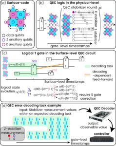
Figure 1: (a) The surface codes (b) A lattice surgery. A fault-tolerant implementation of a two-qubit parity-measurement logical gate (c) An example of a logical non-Clifford T-gate implementation. The logical output of the first lattice surgery (m0) will determine whether to apply a gate modification or not. (d) The logical measurement m0 is a decoding output, dependent on many physical measurements. This logical value is sent to the controller to modify its analogue gate sequence.
Unlike Clifford gates, non-Clifford ones rely on an additional set of requirements. Most importantly, mid-circuit, there is a decoding-dependent feed-forward: to measure, decode, and condition the next pulse on the decoder’s decision, all inside the critical path and while the quantum program is running in a ‘while’ loop. Also, to complete a universal gate-set with the QEC code, every non-Clifford gate is required to have at least one logical initialization of a magic-state, such as the \(|T\rangle=|0\rangle+e^{i\pi/4}|1\rangle\) state, which can be done using methods such as injection, cultivation, or distillation, chosen according to the algorithm’s error budget.
Regardless of how you prepare such the magic state, it is used to perform a logical non-Clifford gate on a computational logical qubit by entangling the two using parity measurement – called-lattice surgery – a fault-tolerant two-qubit gate. This parity measurement has by definition a 50/50 outcome, and the circuit needs to be modified into the feed-forward one to execute the expected result. But this parity measurement is at the logical level and requires decoding. Thus, every non-Clifford gate in the logical circuit requires a corresponding decoding-dependent feed-forward operation, which the controller will execute (or not) as a result of the decoder’s output.
Why should the decoding be fast?
We have found that the key quantity to consider is the feed-forward latency (FFL): the time from the last measurement needed for decoding to the execution of the first decoding-dependent gates. That number largely dictates whether non-Clifford steps run smoothly, degrade, or fail. That’s because the computational logical qubits continue being stabilized and probed while the decoder decodes. If we take a decoding task as all physical (stabilizer) measurements that could modify the decoding result, then while we’re still decoding task A, the hardware will keep producing outcomes that would swell task B.
A longer A makes an even longer B, risking a backlog spiral. In systems terms, if the end-to-end loop QPU→controller→decoder→controller→QPU is too slow, the subsequent decoding task will be larger. This creates a feedback effect: the longer the classical loop takes, the more data it must process next.
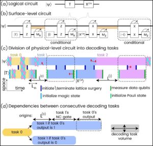
Fig.2: Dependencies between decoding tasks in a circuit with two non-commuting non-Clifford gates. Each task includes all stabilizer measurements which may flip the corresponding feed-forward decision. The size of task 0 is deterministic, but as its corresponding feed-forward latency is larger, task 1 grows, making the second latency larger than the first. If the controller-decoder system is not fast enough, a catastrophic backlog is created, and a logical circuit is prohibited.
Feed-forward latency and the risk of backlog
To determine what feedforward latency is good enough, we’ve introduced new tools to analyze the evolution of a QEC non-Clifford quantum circuit with many non-Clifford gates one after another.
We treated the whole real-time classical stack as the controller–decoder unit (CDU). We used a dynamical system analysis to draw on the same plot the feed-forward latency as a function of the number of syndromes to be decoded, L(N), and the number of syndromes to be decoded in the next decoding task as a function of the latency N(L). Their intersection is the steady-state latency \(L_{\text{ss}}\). If a stable \(L_{\text{ss}}\) exists, it becomes the effective duration—and error exposure – of every non-Clifford step; if not, latency diverges and the pipeline cannot close. This graphical method is hardware- and code-agnostic and extends naturally to fluctuating rates and nonlinearities.
This lens moves beyond “catastrophic vs fine,” which is the common criteria to avoid backlog, and also beyond the specific nominal latency of a specific task as it is sometimes used to evaluate decoding hardware.
We found three qualitatively different regimes:
(i) Divergent— when the decoder’s throughput is smaller than the syndrome generation rate, so there is no steady-state point and QEC computation is essentially impossible;
(ii) Classical-limited—when you can run QEC computation, but \(L_{\text{ss}}\) stretches each non-Clifford step and sets its fidelity budget. The operational ceiling is restricted by the speed of the supporting classical infrastructure rather than the quantum hardware itself;
(iii) Quantum-limited—the overall classical loop is faster than the minimal operation time of what is needed to be executed prior to the decoding-dependent correction. In practice, sublinear decoder scaling and adequate bandwidth keep you out of divergence. This is the ideal state where the supporting infrastructure is so efficient that the system’s performance is limited only by the laws of physics.
Defining practical benchmarks: SIFL and SSFL
To make these requirements measurable, we define two steady-state feed-forward latency benchmarks that stress the full closed loop:
A/D → communication → decoding → communication → conditional D/A
while the quantum program continues to run.
Each benchmark reports a single steady-state FFL that simultaneously checks parallel quantum–classical execution, non-divergence, integration and decoding speed. They’re defined with concrete but minimal circuits and can be run with synthetic measurement streams, no qubits required, and can be generalized to any code (surface, color, or QLDPC) as the pseudocode is code-agnostic.
We start with a minimal, repeatable feed-forward primitive and use it to extract a single steady-state latency number. A compact logical measurement triggers a conditional operation; we repeat until the latency converges and report that steady-state value. We specify distance-5 (Surface-49) and distance-11 (Surface-241) instances with 1 µs rounds so results are reproducible. At a small distance, Steady-state Inter-circuit Feed-forward Latency (SIFL) mainly reflects the fixed round-trip overhead \(\tau_0\) (conversion/handshakes). At a larger distance, the decoder’s throughput and link bandwidth dominate; the benchmark is the intersection of the measured FFL curve with the inverse syndrome-rate line.
If SIFL is the baseline loop, SSFL is the stress test: it replaces the compact measurement with lattice surgery, where decoding tasks overlap and the control loop is under heavier load. Here, the logical measurement is a lattice surgery—the heavier, more realistic stress test because decoding tasks overlap. We included pseudocode and compact d=3/5 configurations (\(\approx 41/111\) physical qubits). In this case, tighter coupling between tasks and larger steady-state latencies than SIFL are expected.
Together, these benchmarks provide a practical way to test not just decoder speed, but the integrated performance of the entire classical critical path required for non-Clifford QEC execution. To demonstrate the results, we tested the approach on current hardware (see Fig.3).
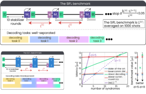
Fig. 3: The circuits and task divisions of the suggested benchmarks, as well as the dynamical system benchmark extraction and benchmark values (bottom right)
To read SIFL, look where the measured latency curve \(L(N)\) crosses the code’s inverse accumulation line \((N(L))^{-1}\). At distance-5, the benchmark is set primarily by the round-loop controller-decoder time, since there are only a few expected syndromes per decoding task. By distance-11, decoder complexity and communication bandwidth modify the steady-state. A sublinear-scaling decoder with a modest round trip can beat a snappier round trip with linear scaling—that’s an example of what a steady-state metric might reveal. At distance-5, the benchmark is set primarily by the round-loop controller-decoder time, since there are only a few expected syndromes per decoding task. By distance-11, decoder complexity and communication bandwidth modify the steady-state. A sublinear-scaling decoder with a modest round trip can beat a snappier round trip with linear scaling—that’s an example of what a steady-state metric might reveal.
Figure 3 also shows state-of-the-art performance (in blue), achieved through QM’s orchestration platform. This system uses an OPX to enable rapid analog-to-digital conversion and feed-forward pulses, which do not rely on local classical processing alone. When paired with high-speed decoding hardware, such as the CPU or the GPU of DGX Quantum – a system that integrates high-performance classical computing with quantum control hardware to accelerate data processing –or even a dedicated FPGA decoder, it can apply pulses based on decoding results. These components communicate via an OPNIC channel, allowing seamless interaction and nanosecond-scale communication latencies.
In the near-term, we expect the round loop to be minimized with the help of DGX Quantum. The GPU can support below-linear throughput and the overall provision bandwidth, so measurement streams don’t throttle compute. Any system can use SIFL to verify a closed loop with existing controller-decoder hardware and develop methods to reach the SSFL to stress decoding of overlapping tasks.
The broader goal here is a shared, system-agnostic yardstick that would show the classical stack is ready when quantum devices reach threshold at the hundreds-of-qubits scale – ensuring the classical and quantum layers advance in step toward executable, error-corrected non-Clifford computation. The ultimate goal is to establish a universal standard that ensures classical and quantum technologies are advancing together, to support large-scale, reliable computation.
Reference: Kurman et al., “Benchmarking the Ability of a Controller to Execute Quantum Error Corrected Non-Clifford Circuits,” in IEEE Transactions on Quantum Engineering, vol. 6, pp. 1-14, 2025, Art no. 5500614,doi: 10.1109/TQE.2025.3608053.

